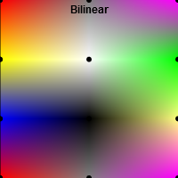
In the context of textures, bilinear interpolation is very important. Your task is to implement bilinear interpolation instead of nearest neighbor interpolation for the setup shown below. Colors are given at the black points; the nearest neighbor interpolation in the left square shows you which colors the points have.

Follow the instructions in the source code and implement the bilinear sampling method Basic1a.sampleBilinear. Make use of the given helper functions. Once you are done, the square in the middle should look like the square on the right.

This subtask is about MIP Mapping. The first aim is to build the MIP map pyramid. Follow the instructions in the constructor MipMap(texture1D, nLevelMax). After implementation you should see the coarser two levels of the MIP map pyramid, which are currently black, depicted in color (beneath the surface).

Next, you should use the MIP map pyramid to set the colors of the pixels in the image plane. Currently we always use the finest level of the pyramid. You have to adapt the code in Basic1b.DetermineMipMapLevelOfPixel(i) accordingly. The idea is to compute the footprint of a pixel in the texture. If the footprint is larger than the texel size of a level, you should use a coarser level. The footprint of a pixel can be computed by the distance of the top and bottom texture coordinate of the pixel (These coordinates are already computed, see comments in the source code!).

You can adjust the number of pixels on the image plane shown below:

This assignment will give you a look at perspective contortion and its consequences for rasterization. A triangle $\Delta ABC$ with $A = (0, 0, -1)^T$, $B = (0, 2, -3)^T$ and $C = (-2, -1, -3)^T$ is given. This triangle contains another triangle which consists of the centers of the edges $AB$, $BC$ and $CA$. Furthermore, a projection matrix $M$ is given which transforms $\Delta ABC$ such that $A'$ lies at the near plane and $B'$ and $C'$ lie on the far plane. $$ M=\left[ \begin{array}{rrrr} 1 & 0 & 0 & 0 \\ 0 & 1 & 0 & 0 \\ 0 & 0 & -2 & -3 \\ 0 & 0 & -1 & 0 \end{array} \right] $$

  1. Compute the transformed and dehomogenized vertices $A'$, $B'$ and $C'$. Make use of the given helper functions (see comments in the source file).
  2. Compute the centers of the edges $P_{A',B'}$, $P_{B',C'}$ and $P_{C',A'}$ from $A'$, $B'$ and $C'$. Is the drawn inner triangle perspectively correct? Which interpolation method do you know that would provide the same result?
  3. Compute the transformed and dehomogenized centers of the edges $P_{A,B}'$, $P_{B,C}'$ and $P_{C,A}'$ from $P_{A,B}$, $P_{B,C}$ and $P_{C,A}$. Is the drawn inner triangle perspectively correct?

Give answers to the theoretical questions in Basic2.txt!

In this task, you should texture a plane, first with a texture containing colors, second with a texture containing normals. Right now, you look at the plane (which is colored grey) from the top. You can change the viewing angle using the W and S keys. There is a point light source hovering over the plane, like in the Phong shading task of Basic Exercises 6.

On the right, you see a checkerboard texture. Several steps are needed to apply this texture to the plane.

  1. Set up the texture from the provided image.
  2. In the vertex shader you can find an attribute for the texture coordinates. Define a varying variable to pass them to the fragment shader. Assign the attribute to the varying variable. Note that the WebGL warning "WebGL warning: vertexAttribPointer: -1 is not a valid index." will disappear once you have done this. The warning appears because when vTexCoord is unused, the shader compiler omits it and its location cannot be found.
  3. In the fragment shader, define the same varying variable to receive the texture coordinates from the vertex shader. Define a uniform sampler holding the texture to be passed, and sample the texture at the texture coordinates.

Once the texture is set up correctly, you see the texture in the upper left corner of the plane, where the texture coordinates are smaller than $1$. To repeat the texture for texture coordinates greater than $1$ rather than clamping it to the nearest value, you can check the associated checkbox. Have a look at onChangeRepeat() to see how it works.

As soon as repeating is enabled, the texture covers the entire plane. When you change the view angle, however, minification occurs in areas farther away, and ugly patterns arise. To change this, enable MIP mapping by checking the associated checkbox. Have a look at onChangeMipmap() to see how it works. In next week's lecture, you will see what MIP mapping is and how it is used to prevent minification artifacts!

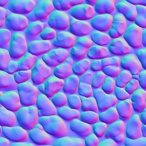
A texture can also be used to store additional information of a surface, such as normals. On the right, you see a so-called normal map which stores normals encoded as RGB triplets. Once these normals are used for lighting computation in the fragment shader, the plane does not look flat anymore, but as if covered with cobblestone. Find the appropriate TODOs in the two submission files and apply the normal map to the plane! You can reuse the texture coordinates already used in the first subtask. Be aware of two things: First, the normals are stored as colors, which means that their values have been mapped to $[0,1]$. You have to bring them back to $[-1,1]$ to use the normals. Second, unlike in the last subtask, the plane should be covered with one single, unrepeated instance of the texture. Therefore, you have to change the texture coordinates to be in range $[0,1]$ rather than $[0,width]$ and $[0,height]$, respectively ($width$ and $height$ are given in the uniform planeSize!).

checkerboard texture cobblestone normal texture

repeat the texture

enable MIP mapping

Spherical coordinates are used to describe positions on a sphere. They consist of two angles $\Theta$ (=theta) and $\Phi$ (=phi) and the distance $r$ of the point to the sphere center. In this exercise we are only interested in surface points of the unit sphere. Therefore, the radius is neglected. Check out the Wolfram article for more informations, but keep in mind that we use a slightly different coordinate system with x pointing to the right and y upwards.

Given a point $X = (x,y,z)$ with $|X| = 1$, the spherical coordinates of $X$ are: \[ \Theta = \text{tan}^{-1} \left( \frac{z}{x} \right) \] \[ \Phi = \text{cos}^{-1} \ y \] Compute the spherical coordinates of a point in the function cartesianToSpherical in helper.glsl. Return the angles in a vector of the form vec2(theta,phi).

The transformation from spherical coordinates back to cartesian coordinates is defined as: \[ x = \text{sin} \ \Phi \ \text{cos} \ \Theta \] \[ y = \text{cos} \ \Phi \] \[ z = \text{sin} \ \Phi \ \text{sin} \ \Theta \] Compute this conversion in sphericalToCartesian.

As you have seen in the basic exercise, the texture coordinates u and v are in the range [0,1]. Unfortunately, $\Theta$ is in the range $[-\pi,\pi]$ and $\Phi$ in the range $[0,\pi]$. Implement the function sphericalToTexture that maps the spherical coordinates to texture coordinates. Note that the texture coordinates must be mirrored to give correct results.

In this task we want to show a universe texture in the background. For this purpose a screen space quad is already rendered behind every other object. Compute the world position of each fragment of the quad in universe.glsl. After that, compute the viewing direction in world space and use the method implemented in the previous exercise to sample the universe texture. If everything is correct your scene should look like this:

Important:
To better visualize the effect of bump mapping on the mesh, we added tesselation to dynamically subdivide each triangle in multiple smaller triangles. You do not have to care about the tesselation process because everything is already implemented, but you have to know that each vertex of the fine mesh is passed through the "Tesselation Evaluation" shader. This "Tesselation Evaluation" shader behaves identically to a vertex shader and variables can be passed to the fragment shader like you have done it before. That is why when we talk about the vertex shader in the following tasks, we actually mean the tesselation evaluation shader. If you are interested and want to know more about tesselation, feel free to read the code, ask the tutors, search the web, and of course join our "Interactive Computer Graphics" lecture in the next semester :).

The basic Phong shading you know from previous exercises is already implemented. In this task we want to show the 'night texture' of the earth (lights around big cities etc.) when the surface is facing away from the light. Read from the day and night texture and blend between these values in earth.glsl. Make sure the transition is smooth. The texture coordinates are passed in the variable tc and should already be correct if you implemented the previous task.

Once you have mapped the color textures to the sphere, you will notice a seam where the left and right edge of the texture meet on the sphere. This is expected behaviour as the texture coordinates of 0 and 1 meet here, you do not need to fix it.

The specular coefficient (not the exponent!) for each earth surface point is stored in the 'earthSpec' texture. Read this value and use it in the lighting computation. You can better observe the effect of the varying specular intensity when disabling color. After this subtask the scene should look like this:

The normals stored in the normal texture are in tangent space. To use them, they have to be converted to world space with the TBN matrix. The TBN matrix is a 3x3 orthonormal matrix consisting of the tangent (T), bitangent (B), and normal (N) as column vectors. The normal N is already known for every vertex. In Exercise 5, you learned a way of constructing an orthonormal basis from a single unit vector. This does not work here, because there are indefnite possible orthonormal bases and we have to choose the one that was used when creating the normal map. Fortunately, every normal map aligns T and B to the texture coordinates.

The tangent and bitangent for spheres with spherical texture coordinates (as we are using here) are very simple to compute. In object space, all T's are in the x-z plane (parallel to the equator) and all B's are perpendicular to T and N. Compute T and B for every vertex in earth.glsl like that: \[T = (0,1,0)^T \times N \] \[B = N \times T \] In the fragment shader, use the interpolated vectors to create the TBN matrix and use it to transform the normal read from the texture to world space. Hint: Don't forget to normalize each vector.

Once you have implemented this part, you can see the result of normal mapping when you switch to 'Vertex TBN'. It should look like the following image:

As described above, the tangent, bitangent, and normal build an orthonomal basis aligned to the uv coordinates. When having knowledge about the partial screen space derivatives both of the world position ($p_x=(p_{x1},p_{x2},p_{x3}),p_y=(p_{y1},p_{y2},p_{y3})$) and of the respective texture coordinates ($c_x=(c_{x1},c_{x2}),c_y=(c_{y1},c_{y2})$), the tangent and bitangent can also be computed directly: \[ T = (p_y \times N) c_{x1} + (N \times p_x) c_{y1}\] \[ B = (p_y \times N) c_{x2} + (N \times p_x) c_{y2}\] The only problem right now is the computation of the screen space derivatives, because for example a central difference in x direction would require each fragment to know the values of the left and right neighbour. Fortunately, OpenGL provides the built-in functions dFdx and dFdy that do these derivatives for you. For example, dFdx takes as input a varying variable from the vertex shader and returns the central difference in x direction.

Use dFdx, dFdy, and the formulas for normal mapping in the fragment shader. If you have implemented this task correctly, it should look exactly like the per vertex normal mapping of task 6.5c).

In addition to a normal map, we also added a height map of the earth in earthBump. You can use this height map to translate every vertex along its normal according to the height sample.

Implement bump mapping in the vertex shader (= tesselation evaluation shader) of earth.glsl. Use the uniform heightScale to control the shifted distance. Translate the vertices in objectSpace.

Play around with the 'tesselation factor' in the GUI to change the number of vertices and therefore the detail level of the earth surface. Different to normal mapping, bump mapping also alters the shape of the earth's silhouette:

In this task you are asked to add clouds to our earth. The clouds are rendered in white with alpha blending enabled. Read the cloud map in clouds.glsl and set the alpha value appropriately to display smooth clouds. Make sure no clouds are visible on the night side of the earth and smoothly blend them in as you did with the day texture.

Next, we want to add fake cloud shadows on the earth. Sample the cloud map in earth.glsl and diminish the incoming light on the earth surface according to the cloud map value. On the night side of the earth this shadowing should not have an effect. When you are done, the final image should look like this: